How to 3d Print Gears
Some complex mechanical 3d prints use gears and geared mechanisms in beautiful ways. To design gears for 3d printing, you have to take some things into account. Clearance, the printer type, and the type of gear. You’re best off using gear creator scripts, or importing existing pieces and correcting scale and clearance issues.
Clearance – 0.6mm
3d printers cannot print perfectly, so there will always be a bit of variation between the model and the output. If you make a round hole that’s 10mm in diameter and a 10mm diameter drive shaft to fill that hole, it won’t have enough clearance to fit into the hole. The best current commercially available printers have a resolution of 0.1mm. This means there could be up to 0.2mm difference between the actual surface of your print and the 3d model. Models also shrink a little after being printed.
You need to design gears to account for shrinkage and resolution issues. To do this, include clearance – empty space between the gears and between the gear axle and the stationary part of the model. The more clearance there is between gearing, the more certain you can be everything will fit together. But at the same time, they will have less mechanical efficiency, so they will require more force to turn. To ensure your model fits, use 0.6mm clearance between all moving parts.
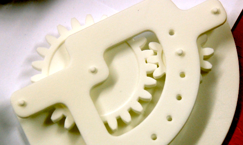
Printer – Use Laser Sintering
If you use a commercial printer, your model will probably be printed with laser sintering. A powder is deposited, and a laser melts the powder into a solid. The powder holds your model in place, so pieces that would have to be printed separately can be printed in place. The powder holds them up as each layer is printed. Ball and socket joints can be 3d printed in place. Gears can be printed in place, instead of needing assembly, because the powder fills the clearance gap.
You can print gear systems on 3d printers that don’t use laser sintering, but you need to use support structures to stand in place of the powder. You can either design them by hand, or let your slicing software generate them. Support structures need to be hand removed. Some 3d printers let you print with a second material that can be dissolved, but most will need to be cleaned off with a utility knife or scalpel. Check out this video to show how much can need to be removed if you want to print in place.
Otherwise, you can print each piece separately and assemble by hand. This is safer, but means you need to design even more fasteners to solidly snap together pieces that hold the gearing. Emmett’s Automatic Transmission model on thingiverse has each piece as an individual model. Once printed, they can be hand assembled.
![]()
Use a Template
Unless you’re a mechanical engineer, it may take you many test prints to get the right fitting and gearings. The woodgears.ca gear template software lets you easily change parameters and generate gears that fit your use. Thingiverse has many gear templates that are tested by other users, so find the one that best fits your application, making sure you pick one that has been actually printed, and insert it into your design. You will likely have to scale the gearing to work with your model. Once the gears are scaled, remember to check that the gear clearance is still 0.6mm, since that may have changed when you scaled the system.
Many of the standard 3d modeling tools also have scripts to generate gears, created by users. Do a search for scripts before you try to hand-model gears yourself. For example, here are scripts for Blender and Rhino. Inkscape has built in gearing support, and can be used in your gear modeling pipeline.
By Hand – Are You Sure?
Read the guide to how gears work. For efficient gears, you can’t use triangles or squares. You need an involute curve, or depending on your application, you could need a more complex shape, like a worm gear. The tips of the gear should not touch the other gear. Instead, where they intersect, the “Pitch Line”, should reach slightly over halfway into the gear – about 1:1.25. If you’re going to try to model gears by hand, find a good design reference to consult. One of the classic reference manuals is Dudley’s Handbook of Practical Gear Design. You really shouldn’t try to make gearing systems by hand unless you have lots of engineering experience.
There are some amazing models being made with gearing. Think of an existing real world model and how you could adapt it to 3d printing. With a few test prints, and using gearing, you can have a 3d print with moving parts.